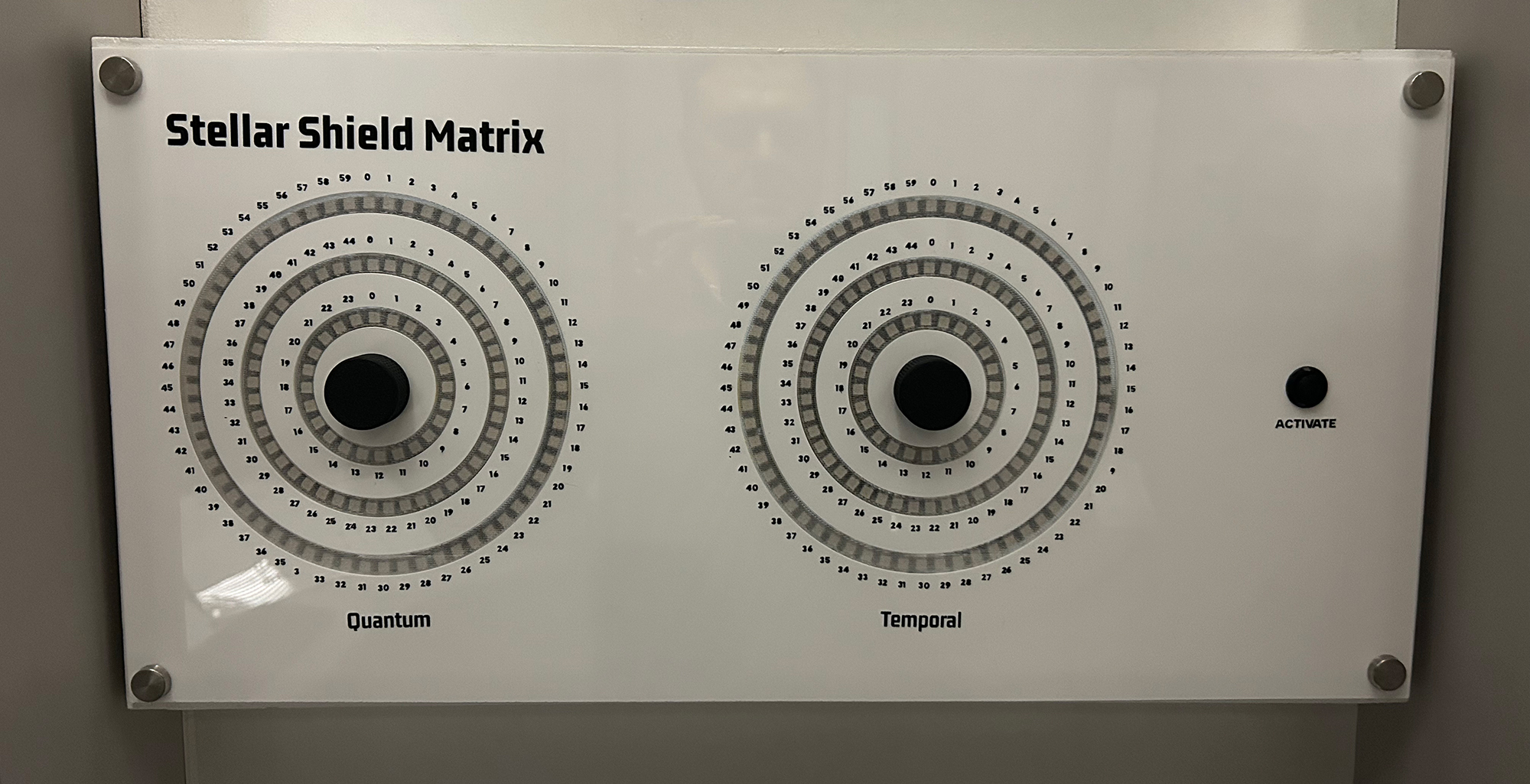
Stellar Shield Matrix
This tutorial creates an advanced dual-matrix puzzle using rotary encoders and LED rings. Players must synchronize Quantum and Temporal matrices by aligning three concentric rings on each side. This puzzle features real-time WebSocket communication for integration with an escape room control systems and creates visual effects with individually addressable LEDs.
Gameplay Mechanics
The Challenge
Players must discover the correct alignment by understanding the relationship between the Quantum and Temporal matrices. The solution requires specific positions on all six rings (3 per matrix).
Through searching for clues, players will discover a series of Shield Matrix codes on the shuttle. Each code creates a unique protective shield.
The puzzle's difficulty comes from the large number of possible combinations: 60 × 45 × 24 positions per matrix = 129,000 total combinations.
How Players Interact
- Select a ring: Press the encoder button to cycle through outer → middle → inner rings
- Adjust position: Rotate the encoder to move the bright LED around the selected ring
- Active feedback: The currently selected ring shows dimmed background lighting
- Check solution: Press the debug button to test if matrices are synchronized
- Visual confirmation: Green flashes indicate success, red flashes indicate failure
Required Components
Hardware
- 1x ESP32 Development Board
- 2x Rotary Encoders with push buttons
- 258x WS2812B LED Ring assemblies (2 - 60+45+24 LEDs each)
- 1x Push button (activation button)
- 5V Power Supply (3A minimum)
- Jumper wires
- 1000µF capacitor (for LED power)
- 470Ω resistors (between GPIO pin and LED Ring)
Software Requirements
- Arduino IDE (1.8.0 or later)
- ESP32 Board Package
- FastLED Library (3.5.0+)
- WebSocketsClient Library
- ArduinoJson Library (6.x)
Wiring Diagram
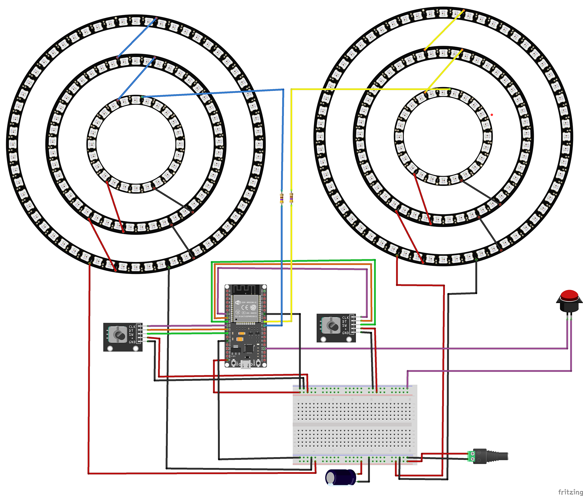
Temporal Encoder
- CLK → GPIO 26
- DT → GPIO 27
- SW → GPIO 14
- + → 5V
- GND → GND
Quantum Encoder
- CLK → GPIO 32
- DT → GPIO 33
- SW → GPIO 25
- + → 5V
- GND → GND
LED Rings
- Left Ring → GPIO 5
- Right Ring → GPIO 18
- VCC → 5V
- GND → GND
Activate Button
- Terminal 1 → GPIO 15
- Terminal 2 → GND
- Internal pull-up enabled
The Code
1Include Required Libraries
Import all necessary libraries for LED control, WiFi connectivity, and JSON communication:
// Core Arduino library
#include <Arduino.h>

// LED control library
#include <FastLED.h>

// Network libraries
#include <WiFi.h>
#include <WebSocketsClient.h>
#include <ArduinoJson.h>
What each library does:
FastLED.h: High-performance library for controlling WS2812B (NeoPixel) LEDs. Provides color manipulation, brightness control, and efficient data transmission to LED strips.
WiFi.h: ESP32's built-in WiFi library for network connectivity. Handles connection to wireless networks and provides network configuration options.
WebSocketsClient.h: Enables real-time bidirectional communication with a WebSocket server. Perfect for escape room integration where instant updates are crucial.
ArduinoJson.h: Efficient JSON parsing and generation library. Used to format messages for the escape room control system in a standard, easily parseable format.
2Network and WebSocket Configuration
Configure your network settings and WebSocket connection parameters:
// WiFi credentials
const char* ssid = "Network SSID";
const char* password = "Network Password";

// WebSocket server configuration
const char* wsHost = "172.16.12.2";
const int wsPort = 1880;
const char* wsPath = "/events";

// Static IP Configuration (optional but recommended)
IPAddress local_IP(172, 16, 12, 10);
IPAddress gateway(172, 16, 12, 1);
IPAddress subnet(255, 255, 255, 0);

// WebSocket client instance
WebSocketsClient webSocket;
bool connected = false;

// Puzzle identification
const char* PUZZLE_ID = "SSM";
Network configuration explained:
Static IP: Using a static IP ensures the puzzle always has the same network address, making debugging and server configuration easier.
WebSocket path: The endpoint on your Node-RED or control server that handles escape room events.
PUZZLE_ID: Unique identifier for this puzzle in your escape room system. SSM stands for "Stellar Shield Matrix".
3LED Ring Configuration
Define the LED ring structure and color scheme:
// LED ring sizes (from inner to outer)
#define INNER_RING_LEDS 24
#define MIDDLE_RING_LEDS 45
#define OUTER_RING_LEDS 60
#define LEDS_PER_RING (OUTER_RING_LEDS + MIDDLE_RING_LEDS + INNER_RING_LEDS)
#define TOTAL_LEDS (LEDS_PER_RING * 2)

// Color scheme for each ring
const CRGB INNER_COLOR = CRGB(255, 255, 0);  // Yellow
const CRGB MIDDLE_COLOR = CRGB(128, 0, 128);  // Purple
const CRGB OUTER_COLOR = CRGB(0, 255, 255);    // Cyan

// LED array
CRGB leds[TOTAL_LEDS];

// Solution values for puzzle completion
const int QUANTUM_SOLUTION[3] = { 45, 18, 9 };   // [outer, middle, inner]
const int TEMPORAL_SOLUTION[3] = { 31, 10, 3 };  // [outer, middle, inner]
LED organization:
Ring structure: Each matrix has three concentric rings. LEDs are indexed sequentially from inner to outer ring.
Color coding: Each ring has a distinct color for easy visual identification. Yellow for inner (core), purple for middle (shield), cyan for outer (field).
Solution arrays: Define the target positions for each ring. Players must align the illuminated LED on each ring to these specific positions.
4Rotary Encoder Handling
Implement interrupt-driven encoder reading for responsive control:
// Encoder interrupt handlers
void IRAM_ATTR updateTemporalEncoder() {
    updateEncoder(1, TEMPORAL_PIN_A, TEMPORAL_PIN_B);
}

void IRAM_ATTR updateQuantumEncoder() {
    updateEncoder(0, QUANTUM_PIN_A, QUANTUM_PIN_B);
}

void IRAM_ATTR updateEncoder(int matrixIndex, int pinA, int pinB) {
    // Debounce protection
    long currentTime = millis();
    if (currentTime - lastInterruptTime[matrixIndex] < 1) return;
    lastInterruptTime[matrixIndex] = currentTime;

    // Read encoder state
    int MSB = digitalRead(pinA);
    int LSB = digitalRead(pinB);
    int encoded = (MSB << 1) | LSB;

    // Determine rotation direction using state machine
    int sum = (lastEncoded[matrixIndex] << 2) | encoded;

    if (sum == 0b1101 || sum == 0b0100 ||
        sum == 0b0010 || sum == 0b1011) {
        encoderValue[matrixIndex]++;
    } else if (sum == 0b1110 || sum == 0b0111 ||
               sum == 0b0001 || sum == 0b1000) {
        encoderValue[matrixIndex]--;
    }

    lastEncoded[matrixIndex] = encoded;
}
Encoder processing explained:
IRAM_ATTR: Places interrupt handler in RAM for faster execution on ESP32.
Debouncing: 1ms timeout prevents false triggers from mechanical bounce.
Gray code decoding: The state machine decodes the quadrature encoder signals to determine rotation direction. The bit patterns represent the four possible state transitions.
Responsive steps: The code uses 2 steps per detent instead of 4 for more responsive control, making the puzzle feel more immediate to player input.
5LED Animation and Display
Create visual feedback for the current state and active ring:
Main LED Update Function
void updateLEDs() {
    FastLED.clear();

    for (int matrix = 0; matrix < NUM_MATRICES; matrix++) {
        int baseOffset = matrix * LEDS_PER_RING;

        // Display Inner Ring position
        leds[baseOffset + ringValues[matrix][0]] = INNER_COLOR;
        if (currentRing[matrix] == 0) {
            leds[baseOffset + ringValues[matrix][0]].maximizeBrightness();
        } else {
            leds[baseOffset + ringValues[matrix][0]].nscale8(128);
        }

        // Display Middle Ring position
        int middleOffset = baseOffset + INNER_RING_LEDS;
        leds[middleOffset + ringValues[matrix][1]] = MIDDLE_COLOR;
        if (currentRing[matrix] == 1) {
            leds[middleOffset + ringValues[matrix][1]].maximizeBrightness();
        } else {
            leds[middleOffset + ringValues[matrix][1]].nscale8(128);
        }

        // Display Outer Ring position
        int outerOffset = baseOffset + INNER_RING_LEDS + MIDDLE_RING_LEDS;
        leds[outerOffset + ringValues[matrix][2]] = OUTER_COLOR;
        if (currentRing[matrix] == 2) {
            leds[outerOffset + ringValues[matrix][2]].maximizeBrightness();
        } else {
            leds[outerOffset + ringValues[matrix][2]].nscale8(128);
        }

        // Add dim background for active ring
        if (currentRing[matrix] < NUM_RINGS) {
            addActiveRingBackground(matrix);
        }
    }

    FastLED.show();
}
Display logic:
Each ring shows one bright LED at the current position value.
The currently selected ring is shown at full brightness while others are dimmed to 50%.
A dim background illumination on the active ring helps players see which ring they're controlling.
Success/Failure Feedback
void blinkAllRings(CRGB color, int numBlinks) {
    for (int blink = 0; blink < numBlinks; blink++) {
        // Turn on all rings with specified color
        for (int matrix = 0; matrix < NUM_MATRICES; matrix++) {
            int baseOffset = matrix * LEDS_PER_RING;
            fillRing(baseOffset, 0, color);  // Inner
            fillRing(baseOffset, 1, color);  // Middle
            fillRing(baseOffset, 2, color);  // Outer
        }
        FastLED.show();
        delay(200);

        // Turn off
        FastLED.clear();
        FastLED.show();
        delay(200);
    }
}
Feedback patterns:
Green flashes (3x) indicate successful synchronization when the solution is found.
Red flashes (3x) indicate incorrect alignment when checking the solution.
The flash pattern provides clear, immediate feedback without disrupting gameplay flow.
6WebSocket Communication
Implement real-time communication with the escape room server:
void sendInitializationMessage() {
    if (!connected) return;

    StaticJsonDocument<512> doc;
    doc["shortName"] = PUZZLE_ID;
    doc["type"] = "INITIATION";

    // Send current state of Quantum matrix
    JsonObject quantum = doc.createNestedObject("quantumMatrix");
    quantum["outer"] = ringValues[0][2];
    quantum["middle"] = ringValues[0][1];
    quantum["inner"] = ringValues[0][0];

    // Send current state of Temporal matrix
    JsonObject temporal = doc.createNestedObject("temporalMatrix");
    temporal["outer"] = ringValues[1][2];
    temporal["middle"] = ringValues[1][1];
    temporal["inner"] = ringValues[1][0];

    doc["solved"] = solved;

    String jsonString;
    serializeJson(doc, jsonString);
    webSocket.sendTXT(jsonString);
}
Message types:
INITIATION: Sent when first connecting to register the puzzle with the server.
UPDATE: Sent whenever a ring position changes, includes matrix name and new values.
SOLVE: Sent when puzzle is solved or becomes unsolved, triggers next puzzle or events.
Testing Your Stellar Shield Matrix
1Initial Setup and Calibration
Upload this test sketch to verify your hardware connections:
void setup() {
    Serial.begin(115200);

    // Test encoders
    pinMode(TEMPORAL_PIN_A, INPUT_PULLUP);
    pinMode(TEMPORAL_PIN_B, INPUT_PULLUP);
    pinMode(QUANTUM_PIN_A, INPUT_PULLUP);
    pinMode(QUANTUM_PIN_B, INPUT_PULLUP);

    // Test LED rings
    FastLED.addLeds<WS2812B, LED_LEFT_PIN, GRB>(leds, 0, LEDS_PER_RING);
    FastLED.addLeds<WS2812B, LED_RIGHT_PIN, GRB>(leds, LEDS_PER_RING, LEDS_PER_RING);

    // Light up each ring in sequence
    for(int i = 0; i < TOTAL_LEDS; i++) {
        leds[i] = CRGB::White;
        FastLED.show();
        delay(10);
    }
}2Troubleshooting Common Issues
Encoder Problems
- Verify pull-up resistors are enabled
- Check for loose connections
- Ensure common pin is grounded
- Try reducing debounce time if unresponsive
- Test with Serial.print in interrupt handler
LED Issues
- Check 5V power supply capacity
- Verify data pin connections
- Test with lower brightness first
- Ensure common ground between ESP32 and LEDs
- Try with fewer LEDs to isolate issues
WebSocket Connection
- Verify WiFi credentials are correct
- Check Node-RED server is running
- Confirm WebSocket path matches server
- Monitor Serial output for connection status
- Test with simple WebSocket client first
Solution Not Triggering
- Press debug button to view current values
- Verify solution arrays match expected values
- Check ring indexing (0=inner, 1=middle, 2=outer)
- Ensure button press triggers checkSynchronization()
- Monitor Serial output for solve messages
3Viewing Current Values
Press the debug button (GPIO 15) to display current ring positions in the Serial Monitor. This shows both matrices' current values and the target solution for debugging:
Current Ring Values:
------------------
Quantum Matrix:
  Outer Ring: 45
  Middle Ring: 18
  Inner Ring: 9

Temporal Matrix:
  Outer Ring: 31
  Middle Ring: 10
  Inner Ring: 3

Target Solution:
Quantum Matrix Target: 45-18-9
Temporal Matrix Target: 31-10-3
------------------
Possible Enhancements
Multiple Solutions
Add arrays of valid solutions that change based on previous puzzles solved or time of day for dynamic gameplay.
Animation Sequences
Implement more elaborate victory animations using the FastLED library's advanced features like color palettes and wave functions.
Hint System
Add proximity detection that makes rings pulse faster as players get closer to the correct positions, providing subtle guidance.
Sound Integration
Add a DFPlayer Mini module to play atmospheric sounds or provide audio feedback for rotation and success events.
Remote Control
Implement WebSocket commands to allow the game master to provide hints, change difficulty, or override the puzzle remotely.
Time Pressure
Add a countdown timer that speeds up the background animation or changes colors as time runs out, increasing tension.
Get in touch!
We are currently looking for educators and students to collaborate with on future projects.
Get in Touch!
hello@escapehumber.ca