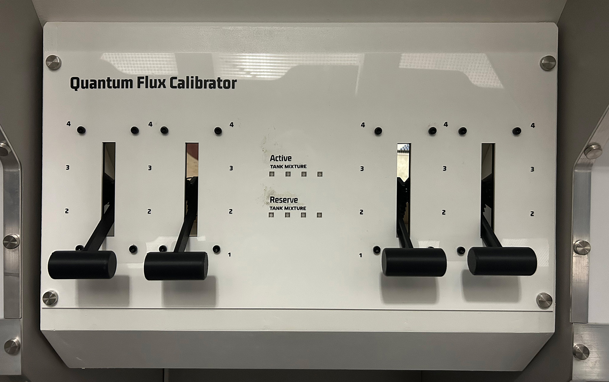
Quantum Flux Calibrator
This tutorial builds an advanced logic puzzle using four potentiometer-based levers and a NeoPixel matrix display. Players must position four levers to specific values that satisfy a complex set of mathematical conditions. The puzzle features real-time WebSocket communication, auto-calibration capabilities, and stunning visual feedback through an 8-LED matrix that displays both reference colors and current lever states.
Gameplay Mechanics
The Challenge
Players must discover lever positions that satisfy four interconnected mathematical conditions. The puzzle requires understanding relationships between levers A, B, C, and D through logical deduction.
The puzzle's difficulty comes from the constrained solution space: while there are 256 possible combinations (4 positions × 4 levers = 4⁴), the mathematical conditions eliminate most invalid combinations, leaving only a few valid solutions.
Hidden complexity: The conditions create dependencies - changing one lever often requires adjusting others to maintain validity.
How Players Interact
- Observe the matrix: Bottom row shows reference colors (Blue, Yellow, Purple, Cyan) representing positions 1-4
- Adjust levers: Turn each potentiometer to change its position value (1-4)
- Watch feedback: Top row displays current lever positions using matching colors
- Listen for tones: Each position change plays a unique musical note (C4, E4, G4, C5)
- Solve the logic: Find the combination that satisfies all four mathematical conditions
- Visual confirmation: Matrix performs rotating color animation when solved

Technical drawing of the Quantum Flux Calibrator
The Four Conditions Explained
Direct Relationships
- Condition A: Lever A + Lever B must equal 5
- Condition D: Lever D must equal 5 - Lever A
These create a mirror relationship: as A increases, B and D must decrease proportionally.
Sequential & Global Constraints
- Condition B: Lever B must be exactly one less than Lever C
- Condition C: The sum of all four levers must be divisible by 3
These add complexity by linking adjacent levers and requiring a specific total sum.
Solution Strategy Tips
- Start with Condition A: Only four valid combinations exist (1+4, 2+3, 3+2, 4+1)
- Use Condition D to immediately determine Lever D once A is set
- Apply Condition B to find valid C values based on your chosen B
- Check if the total sum satisfies Condition C (divisible by 3)
- Listen for the ascending tone sequence when moving through positions 1→2→3→4
Example Valid Solution:
A=2, B=3, C=4, D=3
- ✓ A + B = 2 + 3 = 5 (Condition A satisfied)
- ✓ B = C - 1 → 3 = 4 - 1 (Condition B satisfied)
- ✓ Sum = 2 + 3 + 4 + 3 = 12, which is divisible by 3 (Condition C satisfied)
- ✓ D = 5 - A → 3 = 5 - 2 (Condition D satisfied)
Feedback Systems
Visual Feedback
- Real-time color display of lever positions
- Success animation: rotating colors
- Special display mode when levers are in sequence
Audio Feedback
- Position tones provide immediate confirmation
- Success melody plays when solved
- Musical progression helps players learn positions
Network Feedback
- Real-time updates to game master dashboard
- Progress tracking for hint system
- Integration with room-wide effects
Required Components
Hardware
- 1x Arduino Uno R4 WiFi
- 4x 10kΩ Potentiometers (lever controls)
- 8x WS2812B NeoPixel LEDs (4x2 matrix)
- 2x Push buttons (calibration start/confirm)
- 1x Piezo buzzer
- Jumper wires
- Breadboard
- 470Ω resistor (Between LED strip and Arduino pin)
Software Requirements
- Arduino IDE (2.0 or later)
- Arduino UNO R4 Board Package
- Adafruit NeoPixel Library
- WiFiS3 Library (built-in)
- ArduinoJson Library (6.x)
- WebSocketsClient Library
Wiring Diagram
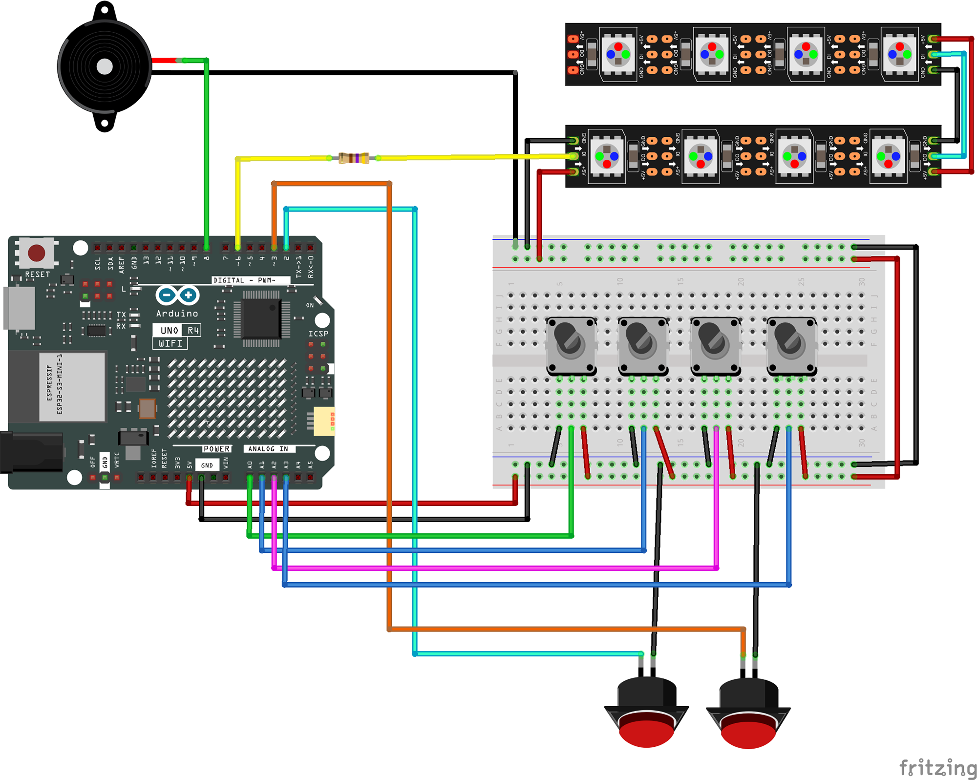
Potentiometers
- Lever A → A0
- Lever B → A1
- Lever C → A2
- Lever D → A3
- All VCC → 5V
- All GND → GND
Control Buttons
- Calibration Start → Pin 2
- Calibration Confirm → Pin 3
- Internal pull-ups enabled
- Other pin → GND
Output Devices
- NeoPixel Data → Pin 6
- NeoPixel VCC → 5V
- NeoPixel GND → GND
- Buzzer → Pin 8
- Buzzer GND → GND
The Code
1Include Required Libraries
Import all necessary libraries for LED control, WiFi connectivity, and data storage:
// LED control and data storage
#include <Adafruit_NeoPixel.h>
#include <EEPROM.h>

// Network and communication libraries
#include <WiFiS3.h>
#include <ArduinoJson.h>
#include <WebSocketsClient.h>
What each library does:
Adafruit_NeoPixel.h: Controls WS2812B individually addressable LEDs. Provides color manipulation and efficient data transmission for the visual feedback matrix.
EEPROM.h: Allows persistent storage of calibration data. The calibration values survive power cycles, eliminating the need to recalibrate after each restart.
WiFiS3.h: Arduino R4 WiFi's specific networking library. Handles connection to wireless networks with support for static IP configuration.
ArduinoJson.h: Efficient JSON parsing and generation for structured communication with the escape room control server.
WebSocketsClient.h: Enables real-time bidirectional communication, perfect for instant status updates and remote monitoring.
2Network Configuration and Pin Definitions
Configure your network settings and hardware connections:
// WiFi and WebSocket settings
const char* ssid = "Network SSID";
const char* password = "Network Password";
const char* wsHost = "172.16.12.2";
const int wsPort = 1880;
const char* wsPath = "/events";

// Static IP configuration
IPAddress staticIP(172, 16, 12, 12);
IPAddress gateway(172, 16, 12, 1);
IPAddress subnet(255, 255, 255, 0);

// Puzzle identification
const char* PUZZLE_ID = "QFC";

// Pin definitions
#define POT_A A0
#define POT_B A1
#define POT_C A2
#define POT_D A3
#define CALIBRATION_START_BUTTON 2
#define CALIBRATION_CONFIRM_BUTTON 3
#define NEOPIXEL_PIN 6
#define BUZZER_PIN 8
Configuration explained:
Static IP: Ensures consistent network address for reliable server communication and easier debugging.
PUZZLE_ID: "QFC" stands for "Quantum Flux Calibrator" - unique identifier in the escape room ecosystem.
Analog pins: Four potentiometers provide 1024 discrete positions each (10-bit ADC), mapped to 4 positions per lever.
3LED Matrix and Color Configuration
Set up the visual feedback system with color-coded levers:
// Matrix definitions
#define MATRIX_WIDTH 4
#define MATRIX_HEIGHT 2
#define NUM_PIXELS (MATRIX_WIDTH * MATRIX_HEIGHT)
#define BRIGHTNESS 50

// Audio feedback frequencies (in Hertz)
const int TONE_POS_1 = 262;  // C4
const int TONE_POS_2 = 330;  // E4
const int TONE_POS_3 = 392;  // G4
const int TONE_POS_4 = 523;  // C5

// Color-blind friendly palette (stored in PROGMEM)
const uint32_t COLOR_BLUE PROGMEM = 0x0000FF;
const uint32_t COLOR_YELLOW PROGMEM = 0xFFFF00;
const uint32_t COLOR_PURPLE PROGMEM = 0x800080;
const uint32_t COLOR_CYAN PROGMEM = 0x00FFFF;

Adafruit_NeoPixel pixels(NUM_PIXELS, NEOPIXEL_PIN, NEO_GRB + NEO_KHZ800);
Matrix organization:
Layout: 4x2 matrix with bottom row showing reference colors and top row showing current lever positions.
Color mapping: Position 1=Blue, 2=Yellow, 3=Purple, 4=Cyan. Colors chosen for maximum distinguishability including for colorblind players.
Audio feedback: Each position plays a unique tone in a C major triad progression, providing multi-sensory confirmation.
PROGMEM storage: Color constants stored in flash memory to conserve RAM on the Arduino.
4Calibration System
Implement a sophisticated calibration routine for accurate lever positioning:
// Calibration structure
struct CalibrationData {
  int positions[4][4];  // [lever][position_1, position_2, position_3, position_4]
  int tolerances[4];    // Tolerance for each lever
} calibration;

void calibratePotentiometers() {
    Serial.println("Starting calibration...");

    // Iterate through positions first, then levers
    for (int position = 1; position <= 4; position++) {
        for (int lever = 0; lever < 4; lever++) {
            // Visual feedback - highlight active lever
            for (int i = 0; i < 4; i++) {
                setMatrixPixel(i, 1, i == lever ?
                    getLeverColor(position) : COLOR_DEFAULT);
            }
            pixels.show();

            // Wait for button press
            while (digitalRead(CALIBRATION_CONFIRM_BUTTON) == HIGH) {
                // Breathing effect while waiting
                int brightness = (sin(millis() / 500.0) + 1) * 127;
                pixels.setBrightness(brightness);
                pixels.show();
            }

            // Read and store the potentiometer value
            int value = analogRead(A0 + lever);
            calibration.positions[lever][position - 1] = value;

            // Play confirmation tone
            playPositionTone(position);
        }
    }

    // Save to EEPROM
    EEPROM.put(0, calibration);
}
Calibration process:
Position-first approach: Calibrates all levers for position 1, then 2, etc., ensuring consistent positioning across levers.
Visual guidance: Active lever highlighted with breathing effect, reference colors shown on bottom row.
Persistent storage: Calibration data saved to EEPROM, surviving power cycles and reducing setup time.
Audio confirmation: Each successful calibration point plays its corresponding tone for immediate feedback.
5Complex Logic Solution
The puzzle requires satisfying four mathematical conditions simultaneously:
Solution Checking Logic
// Function to check complex logic
bool checkComplexLogic() {
    return checkConditionA() &&
           checkConditionB() &&
           checkConditionC() &&
           checkConditionD();
}

// Condition A: Sum of A and B equals 5
bool checkConditionA() {
    return (leverA + leverB) == 5;
}

// Condition B: B is one less than C
bool checkConditionB() {
    return leverB == (leverC - 1);
}

// Condition C: Sum of all levers is divisible by 3
bool checkConditionC() {
    return (leverA + leverB + leverC + leverD) % 3 == 0;
}

// Condition D: D equals 5 minus A
bool checkConditionD() {
    return leverD == (5 - leverA);
}
Mathematical constraints:
Condition A: Creates a dependency between levers A and B (possible combinations: 1+4, 2+3, 3+2, 4+1)
Condition B: Links lever B to C with a sequential relationship
Condition C: Requires the total sum to be divisible by 3, adding a global constraint
Condition D: Creates a mirror relationship between A and D
Solution: The constraints have multiple valid solutions, but one example is: A=1, B=4, C=5 (invalid), requiring players to find A=2, B=3, C=4, D=3 (sum=12, divisible by 3)
Visual Feedback System
// Update lever feedback with special mode for ordered sequence
void updateLeverFeedback(bool leversInOrder) {
    if (!puzzleSolved) {
        if (leversInOrder) {
            // Reverse display order when levers are 1-2-3-4
            setMatrixPixel(0, 1, getLeverColor(leverD));
            setMatrixPixel(1, 1, getLeverColor(leverC));
            setMatrixPixel(2, 1, getLeverColor(leverB));
            setMatrixPixel(3, 1, getLeverColor(leverA));
        } else {
            // Normal display order
            setMatrixPixel(0, 1, getLeverColor(leverA));
            setMatrixPixel(1, 1, getLeverColor(leverB));
            setMatrixPixel(2, 1, getLeverColor(leverC));
            setMatrixPixel(3, 1, getLeverColor(leverD));
        }
    }
}6WebSocket Communication
Real-time status updates to the escape room control system:
// Send initialization message upon connection
void sendInitializationMessage() {
    if (!connected) return;

    StaticJsonDocument<200> doc;
    doc["shortName"] = PUZZLE_ID;
    doc["type"] = "INITIATION";

    JsonObject encoders = doc.createNestedObject("encoders");
    encoders["1"] = leverA;
    encoders["2"] = leverB;
    encoders["3"] = leverC;
    encoders["4"] = leverD;

    doc["solved"] = puzzleSolved;

    char jsonBuffer[200];
    serializeJson(doc, jsonBuffer);
    webSocket.sendTXT(jsonBuffer);
}

// Send lever update when position changes
void sendLeverUpdateMessage(int encoderId, int position) {
    if (!connected) return;

    StaticJsonDocument<200> doc;
    doc["shortName"] = PUZZLE_ID;
    doc["type"] = "UPDATE";
    doc["encoder"] = encoderId;
    doc["position"] = position;

    char jsonBuffer[200];
    serializeJson(doc, jsonBuffer);
    webSocket.sendTXT(jsonBuffer);
}
Message types:
INITIATION: Sent on connection to register puzzle and report all lever positions
UPDATE: Sent whenever any lever changes position for real-time monitoring
SOLVE: Sent when puzzle is solved or becomes unsolved after being solved
All messages use efficient StaticJsonDocument with pre-allocated buffers to minimize memory fragmentation
Testing Your Quantum Flux Calibrator
1Initial Hardware Verification
Upload this test sketch to verify all components:
void setup() {
    Serial.begin(9600);

    // Test potentiometers
    Serial.println("Testing Potentiometers...");

    // Test buttons with pull-ups
    pinMode(CALIBRATION_START_BUTTON, INPUT_PULLUP);
    pinMode(CALIBRATION_CONFIRM_BUTTON, INPUT_PULLUP);

    // Test NeoPixel matrix
    pixels.begin();
    pixels.setBrightness(50);

    // Cycle through all colors on all pixels
    uint32_t colors[] = {COLOR_BLUE, COLOR_YELLOW, COLOR_PURPLE, COLOR_CYAN};
    for(int color = 0; color < 4; color++) {
        for(int i = 0; i < NUM_PIXELS; i++) {
            pixels.setPixelColor(i, pgm_read_dword(&colors[color]));
            pixels.show();
            delay(100);
        }
    }

    // Test buzzer with scale
    tone(BUZZER_PIN, TONE_POS_1, 100);
    delay(150);
    tone(BUZZER_PIN, TONE_POS_2, 100);
    delay(150);
    tone(BUZZER_PIN, TONE_POS_3, 100);
    delay(150);
    tone(BUZZER_PIN, TONE_POS_4, 100);
}

void loop() {
    // Print potentiometer values
    Serial.print("A:");
    Serial.print(analogRead(POT_A));
    Serial.print(" B:");
    Serial.print(analogRead(POT_B));
    Serial.print(" C:");
    Serial.print(analogRead(POT_C));
    Serial.print(" D:");
    Serial.println(analogRead(POT_D));

    // Print button states
    if(digitalRead(CALIBRATION_START_BUTTON) == LOW) {
        Serial.println("Start button pressed!");
    }
    if(digitalRead(CALIBRATION_CONFIRM_BUTTON) == LOW) {
        Serial.println("Confirm button pressed!");
    }

    delay(500);
}
What this test verifies:
- NeoPixel matrix: Each LED lights up sequentially in all four colors, confirming data connection and color accuracy
- Buzzer: Plays the four position tones in sequence (C4, E4, G4, C5) to verify audio feedback
- Potentiometers: Continuously displays raw analog values (0-1023) for each lever in Serial Monitor
- Buttons: Reports when either calibration button is pressed
Expected Serial Monitor output:
Testing Potentiometers...
A:512 B:256 C:768 D:1023
A:512 B:256 C:768 D:1023
Start button pressed!
A:512 B:256 C:768 D:1023
Confirm button pressed!
A:512 B:256 C:768 D:1023
Interpreting the results:
- Potentiometer values: Should change smoothly from 0-1023 as you rotate. Jumpy values indicate poor connections or damaged pots
- LED sequence: All 8 LEDs should light in order. Missing LEDs indicate wiring issues or damaged pixels
- Button response: Messages should appear immediately when pressed. No response indicates wiring or pull-up issues
- Audio tones: Should hear four distinct ascending notes. No sound indicates buzzer wiring issues
2Troubleshooting Common Issues
Potentiometer Issues
- Check wiper (middle pin) connections
- Verify 5V and GND on outer pins
- Test raw values with Serial.print
- Clean potentiometer contacts if erratic
- Ensure stable mounting to prevent drift
NeoPixel Problems
- Verify data pin connection (Pin 6)
- Check 5V power supply adequacy
- Test with simple single-LED sketch
- Ensure correct pixel count (8)
- Add 470Ω resistor on data line
WiFi Connection
- Verify WiFiS3 library (not WiFi.h)
- Check SSID and password spelling
- Confirm static IP isn't in use
- Monitor Serial for connection status
- Test with DHCP before static IP
Calibration Problems
- Clear EEPROM before first calibration
- Ensure buttons have pull-ups enabled
- Check button wiring (normally open)
- Verify potentiometer full range motion
- Allow time for value stabilization
3Serial Monitor Debug Output
The system provides detailed debug information during operation:
WiFi connected
IP address: 172.16.12.12
Gateway: 172.16.12.1
WebSocket connected to: /events

Current Values:
---------------
Lever A: Position 2
Lever B: Position 3
Lever C: Position 4
Lever D: Position 3
---------------
Checking conditions...
Condition A (A+B=5): PASS ✓
Condition B (B=C-1): PASS ✓
Condition C (Sum%3=0): PASS ✓
Condition D (D=5-A): PASS ✓
Success! Puzzle solved!

Sent: {"shortName":"QFC","type":"SOLVE","solved":true}4Calibration Process
To calibrate the levers for accurate position detection:
- Press and hold the calibration start button (Pin 2)
- For each position (1-4), move all levers to that position when prompted
- Press the confirm button (Pin 3) after positioning each lever
- The breathing LED effect indicates waiting for confirmation
- A tone plays after each successful calibration point
- Calibration saves automatically to EEPROM when complete
The calibration data persists through power cycles, so you only need to calibrate once unless the hardware changes.
5Understanding the Zig-Zag Matrix Layout
The NeoPixel matrix uses a zig-zag wiring pattern:
// Matrix pixel arrangement (physical layout)
// Row 0 (bottom): [3] [2] [1] [0]  ← Right to left
// Row 1 (top):    [4] [5] [6] [7]  → Left to right

void setMatrixPixel(int x, int y, uint32_t color) {
    int pixelIndex;
    if (y % 2 == 0) {
        // Even rows run right to left
        pixelIndex = y * MATRIX_WIDTH + (MATRIX_WIDTH - 1 - x);
    } else {
        // Odd rows run left to right
        pixelIndex = y * MATRIX_WIDTH + x;
    }
    pixels.setPixelColor(pixelIndex, color);
}
This wiring pattern is common in LED matrices as it allows for continuous data flow without long return wires.
6Testing WebSocket Communication
To verify WebSocket connectivity independently:
// Simple WebSocket test function
void testWebSocket() {
    if (connected) {
        StaticJsonDocument<128> doc;
        doc["shortName"] = PUZZLE_ID;
        doc["type"] = "TEST";
        doc["timestamp"] = millis();

        char buffer[128];
        serializeJson(doc, buffer);
        webSocket.sendTXT(buffer);

        Serial.println("Test message sent");
    } else {
        Serial.println("WebSocket not connected");
    }
}
Get in touch!
We are currently looking for educators and students to collaborate with on future projects.
Get in Touch!
hello@escapehumber.ca